← Back to All Guides & Journal
Electrical
Electrical Load Calculations and the 80% Rule for Residential ASIC Deployments
Author: Jae-hoon Kim (Lead Electrical Systems Engineer)
Published: January 14, 2025
Read Time: 8 min read
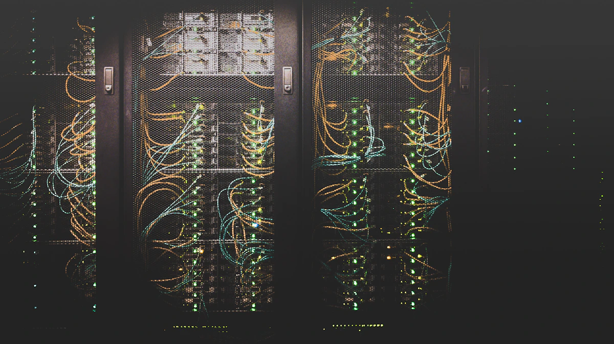
Operating high-draw ASIC hardware in a residential building requires a strict departure from ordinary consumer appliance rules. A standard household microwave or vacuum cleaner pulls power intermittently for minutes at a time. In contrast, an ASIC miner such as an Antminer S19 Pro or Whatsminer M30S draws between 3,100W and 3,400W continuously—24 hours a day, 7 days a week, 365 days a year.
In this guide, we walk through the foundational electrical engineering formulas and safety codes every home operator must calculate before plugging in a single unit.
---
### The Continuous Duty Cycle and the 80% Rule
Under national electrical safety standards (including the Korean Electrical Code and NFPA 70), any electrical load that operates without interruption for three hours or longer is legally classified as a **continuous load**.
For continuous loads, an electrical circuit—including its circuit breaker, conductor wire, and receptacle—must not be loaded beyond **80% of its maximum rated capacity**.
Let us examine the mathematical reality on both 220V and 240V single-phase supplies:
1. **Standard 16A / 220V Household Outlet:**
$$\text{Rated Peak Capacity} = 16\text{A} \times 220\text{V} = 3,520\text{W}$$
$$\text{Maximum Continuous Load (80\%)} = 3,520\text{W} \times 0.80 = 2,816\text{W}$$
*Result:* A 3,250W ASIC unit will overheat the conductors and trip the breaker over time, posing an active fire hazard.
2. **Dedicated 20A / 220V Dedicated Circuit:**
$$\text{Rated Peak Capacity} = 20\text{A} \times 220\text{V} = 4,400\text{W}$$
$$\text{Maximum Continuous Load (80\%)} = 4,400\text{W} \times 0.80 = 3,520\text{W}$$
*Result:* Safely supports a single 3,250W ASIC unit with an adequate 270W safety margin.
3. **Dedicated 30A / 220V Subpanel Drop (Recommended):**
$$\text{Rated Peak Capacity} = 30\text{A} \times 220\text{V} = 6,600\text{W}$$
$$\text{Maximum Continuous Load (80\%)} = 6,600\text{W} \times 0.80 = 5,280\text{W}$$
*Result:* Safely supports up to two under-volted ASIC units or one full-power unit plus high-static exhaust blowers and auxiliary cooling.
---
### Conductor Gauge Selection and Voltage Drop
Under continuous 15A–25A current flow, wire resistance causes significant heat dissipation inside conduit and junction boxes. Undersized wire causes voltage drops, forcing the internal power supply unit (PSU) to draw even higher current to maintain its direct-current (DC) output rails.
When running dedicated lines from your main distribution board:
- **12 AWG (3.5 mm²):** Acceptable for dedicated single 20A circuits where the one-way cable run is strictly under 15 meters.
- **10 AWG (5.5 mm²):** Essential for 30A circuits or runs exceeding 15 meters to prevent voltage drop from falling below the acceptable 3% threshold.
- **8 AWG (8.0 mm²):** Recommended for subpanel feeder lines supporting multiple drops in detached garages or utility sheds.
---
### Breaker Curve Characteristics: Why Type C Matters
Standard residential circuit breakers are typically **Type B**, engineered to trip instantly when inrush current exceeds 3 to 5 times rated capacity.
When an ASIC power supply energizes, its large electrolytic capacitors produce a momentary millisecond inrush spike. On a Type B breaker, this inrush can cause nuisance tripping even when the continuous running draw is completely safe.
In our workshop lab sessions, we demonstrate installing **Type C breakers** (which tolerate inrush currents between 5 to 10 times nominal load) or **Type D breakers** for industrial distribution setups, ensuring clean startup without compromising thermal overload protection.
---
### Practical Safety Checklist Before Energizing
1. Always verify conductor screw torque values using an insulated torque screwdriver (typically 2.0 to 2.5 N·m on terminal blocks). Loose lugs cause high-resistance arc faults under continuous thermal cycling.
2. Install a dedicated Surge Protection Device (SPD, Type 2) at the subpanel to protect sensitive hashboard buck regulators from grid transients and lightning strikes.
3. Keep grounding resistance below 100 Ohms (Type 3 ground) to ensure safe fault clearing in the event of an insulation breakdown.
Practice These Calculations in Our Gimpo Lab
Every topic discussed in our engineering articles is trained with real multimeters, thermal cameras, and live ASIC hardware during our weekend lab intensives.